Quick Start (5 Minutes)
Use this hands-on walkthrough to experience a complete TrueFidelity workflow in about five minutes. It assumes you have already installed the app and completed first-boot activation.
Scenario Overview
Goal: Create a simple ECU system with a CAN network, configure the elements, and verify everything works.
Time estimate: 5–7 minutes.
Prerequisites:
- TrueFidelity Desktop installed and license activated
- Docker Desktop running
- (Optional) A DBC file for signal decoding
Step 1 – Create a New System
- Launch TrueFidelity.
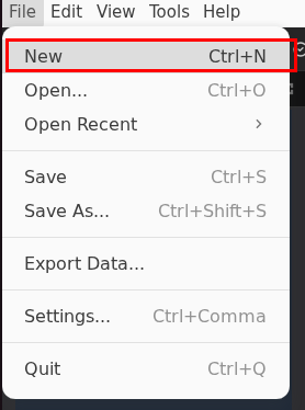
- Go to File → New (or press
Ctrl+N/Cmd+N).
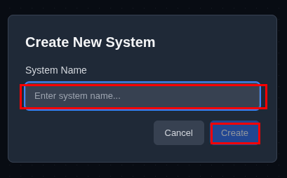
- In the New System dialog:
- System name: Enter
quick-start-demo - Save location: Select your preferred folder
- Click Create.
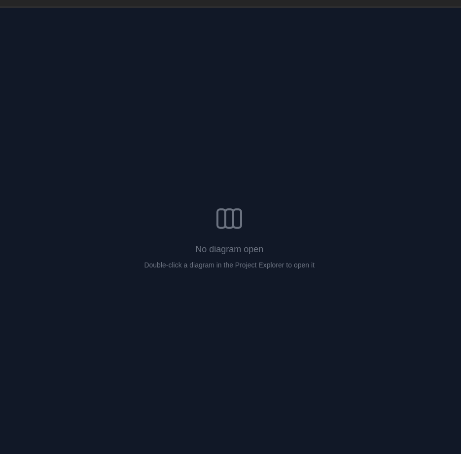
The System Design workspace opens with an empty canvas ready for your topology.
Tip
Systems store your ECU configurations, network topology, and diagram layouts. Create dedicated systems for different test scenarios.
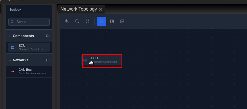
Step 2 – Add an ECU
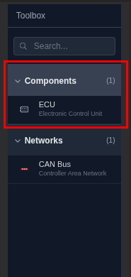
- Locate the Toolbox panel on the left side.
- Expand the Components category.
- Drag an ECU onto the canvas.
- Position the ECU in the upper area of the canvas.
Step 3 – Add a CAN Network
- In the Toolbox, expand the Networks category.
- Drag a CAN Bus onto the canvas below the ECU.
- The CAN bus appears as a red horizontal bar.
Step 4 – Connect ECU to Network
- Hover over the ECU to reveal blue connection handles.
- Click and drag from a handle toward the CAN bus.
- Release when the bus highlights to create the connection.
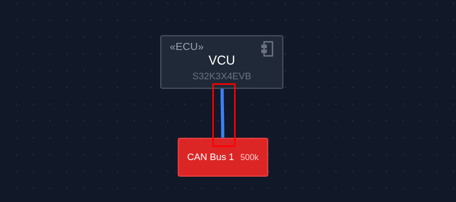
Connection Tips
- Drag from ECU handle to network bus
- A blue line indicates a successful connection
- Multiple ECUs can connect to the same bus
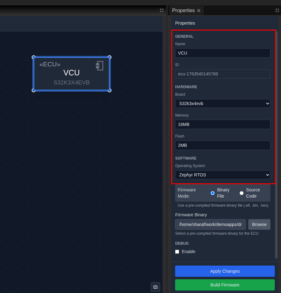
Step 5 – Configure the ECU
- Click the ECU to select it.
- In the Properties panel on the right, configure:
- Name:
Gateway - Board:
S32K3X4EVB(NXP S32K3 evaluation board) - Memory:
16MB - Operating System:
Zephyr - Click Apply Changes.
Step 6 – Save Your System
- Press Ctrl+S (or Cmd+S on macOS).
- Confirm the save location.
- The status bar shows "System saved" when complete.
Save Often
Save your work frequently using Ctrl+S / Cmd+S to avoid losing changes. There is no auto-save feature currently.
Step 7 – Start the System (Optional)
If you have Docker running and want to see monitoring:
- Click the Start button (green play icon) in the toolbar.
- Wait for ECUs to reach "Running" status.
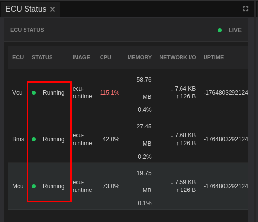
- Open the ECU Monitoring layout via View → Layouts → ECU Monitoring.
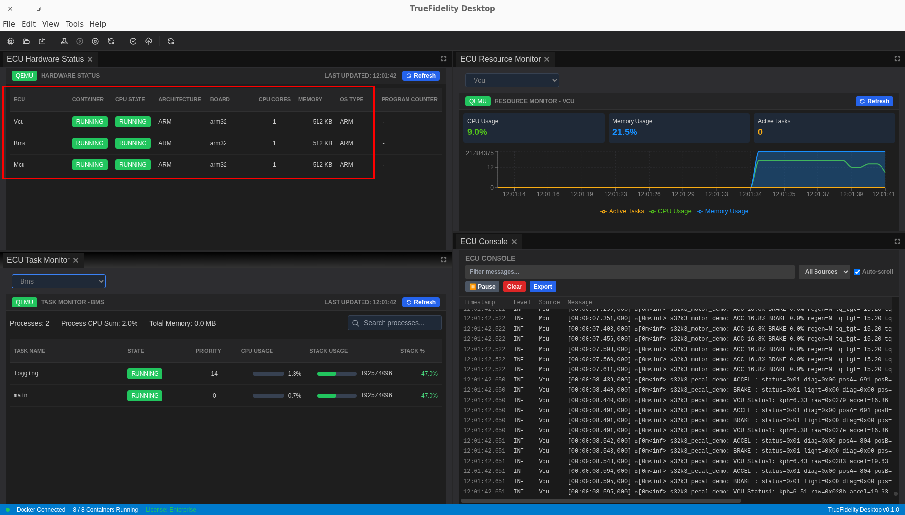
- Observe real-time metrics in the ECU Status and Resource Monitor panels.
Terminal Availability
Terminal access is only available for Linux-based ECUs. For Zephyr RTOS ECUs (like this example), use the ECU Console panel to view runtime logs instead.
Step 8 – Stop and Clean Up
- Click the Stop button (red square) in the toolbar.
- Wait for all ECUs to show "Stopped" status.
- Close the system via File → Close or continue experimenting.
What You've Accomplished
In just a few minutes, you've:
- Created a new TrueFidelity system
- Added an ECU and CAN network to the topology
- Connected the ECU to the network bus
- Configured ECU properties
- Saved your system configuration
- (Optionally) Started and monitored the running system
Next Steps
- Full Tutorial: Follow the System Design Workflow for a comprehensive 30-minute walkthrough with multiple ECUs.
- Signal Analysis: Learn about DBC & Signal Definitions to decode CAN messages.
- Workspaces: Explore Workspaces & Layouts to customize your interface.
- Playback: Set up signal playback in the Playback Analysis tutorial.